info@airmep.in | +91-9810220896 | New Delhi, Delhi, 110015
Rigid Coupling vs Flexible Coupling – Key Differences, Types, Applications & Benefits
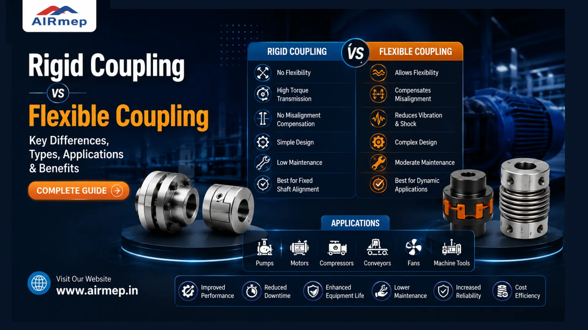
A coupling is a mechanical device utilized to link two shafts together to transmit power and torque. The basic difference is that rigid couplings make a strong connection demanding ideal shaft alignment, while flexible couplings absorb vibrations and compensate for small shaft misalignments.
In industrial engineering and mechanical design, linking two rotating shafts or joining pipelines seamlessly is basic to machine life. The elements responsible for this task are mechanical couplings. Whether you’re negotiating with huge rotating motor shafts or making a high-pressure commercial piping network, selecting the appropriate coupling determines how long your tools survive.
Table of Contents
What is Rigid Coupling?
A rigid coupling is developed to make a thoroughly fixed, strong connection between two shafts or pipes. Once installed, it blocks the linked parts together to work as a single, constant unit.
Core Features –
1. Zero Misalignment Tolerance – It demands ideal alignment during installation. If the shafts or pipes are even slightly crooked, the coupling will not turn to accommodate them.
2. Maximum Torque Transfer – Because it is strong, it transmits rotational power with extreme effectiveness and near-zero backlash.
3. No Vibration Dampening – It doesn’t absorb shock. Any vibration from the motor travels directly into the driven machine.
What is Flexible Coupling?
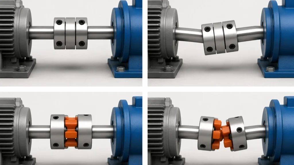
A flexible coupling is particularly developed to look after real-world imperfections. It comprises moving sections or elastic elements that permit the linked shafts or pipes to move slightly without breaking.
Core Features –
1. Misalignment Friendly – It effortlessly manages minor positioning mistakes between shafts.
2. Vibration and Shock Absorption – The soft or semi-flexible inner components work like a car cushion, soaking up sudden torque spikes and smoothing out functions.
3. Secures Equipment – By absorbing stress, it controls early wear and tear on costly motor bearings and seals.
Rigid Coupling vs Flexible Coupling – Key Differences
To assist you in comparing rigid vs flexible couplings rapidly, here is a breakdown of how they stack up across functional metrics –
| Operational Feature | Rigid Coupling | Flexible Coupling |
| Alignment Requirement | Must be perfectly aligned. | Can handle minor misalignments. |
| Vibration & Shock Absorption | None. Transmits all shocks directly. | High. Absorbs system vibrations and noise. |
| Torque Transmission | Exceptionally high and highly precise. | Moderate to high (some energy can absorb in the flexible parts). |
| Backlash (Play) | Extremely low or near-zero. | Varies from low to moderate depending on design. |
| Maintenance Need | Low, but requires frequent alignment checks. | Moderate (flexible inserts can wear out and need replacing). |
| Upfront Cost | Budget-friendly and simple. | Higher initial cost due to complex parts. |
Types of Rigid Coupling and Flexible Coupling
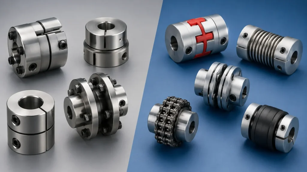
To complement your digital guide, here is a structured breakdown of the most typical kinds of rigid and flexible couplings utilized across mechanical and industrial applications today.
Rigid Couplings –
Rigid couplings are utilized when shafts are already ideally aligned and demand rock-solid power transmission with zero movement between them.
1. Sleeve or Muff Coupling – A simple, hollow cylinder that slides over both shafts. The shafts are locked in place utilizing a common keyway and set screws. It is the most economical rigid choice.
2. Split-Muff or Clamp Coupling – Similar to a sleeve coupling, but split into two separate halves. You bolt the halves together over the shafts, making it effortless to install or eliminate without moving your heavy machinery.
3. Flange Coupling – Comprises two separate flanged hubs keyed to each shaft end. The faces of the flanges are bolted together tightly. They are developed for heavy-duty torque loads and can link shafts of various diameters.
4. Taper-Lock Rigid Coupling – Utilizes a specialized tapered bush that clamps onto the shafts as screws are tightened. This delivers a thoroughly uniform, tight grip around the shaft circumference without leading to surface harm.
Flexible Couplings –
Flexible Couplings feature built-in elastic components or moving connections developed to bend, slide, or twist slightly to house minor shaft misalignments
1. Gear Coupling – Facilitates inner hubs with outer gear teeth that mesh inside a sleeve with internal teeth. The teeth are curved, permitting them to misalign a little bit while transferring huge torque loads.
2. Disc or Diaphragm Coupling – Utilizes ultra-thin, adaptable stainless-steel disc packs bolted optionally to the driving and pushed hubs. It delivers outstanding adaptability with zero backlash and demands no lubrication.
3. Grid Coupling – Facilitates a spring-like metal grid woven into slots on two cents. It is highly useful at absorbing sudden shock loads and cutting down system vibrations by up to 30%.
4. Oldham Coupling – Comprises two drive hubs and a floating hub plastic slider disk. The slider slots onto the hubs at a 90-degree offset, making it amazing for applications with parallel misalignment.
Applications – When to Choose Which?
Every mechanical formation has its own functional priorities. Here is where you will see these industrial couplings working in various industries –
Where to Use Rigid Couplings –
1. Precision CNC Machining – Precision components require crucial synchronization with zero backlash to implement smooth cutting, turning, and milling.
2. Vertical Pumps – Vertical turbine pumps utilize rigid sleeves to maintain the heavy internal rotor ideally focused.
3. High-Speed Turbines – Huge power generation units need continuous torque transmission in ideally aligned parts.
Where to Use Flexible Couplings –
1. Conveyor Belt Systems – Typical star-stop cycles make jarring torque spikes that adaptable joints securely cushion.
2. HVAC Systems – Linking blowers, chillers, and fans demands adaptable connections to isolate noise and block vibrations from going into building structures.
3. Automation and Robotics – Multi-axis robotic arms use specialized miniature flexible couplings to seamlessly execute quick movements without straining small servo motors.


Benefits of Rigid Couplings and Flexible Couplings
Below are the strong benefits of these mechanical couplings –
Rigid Couplings –
Rigid couplings are chosen for systems where performance depends on crucial positional precision, high structural power, and uncompromised power transfer.
1. Torsional Stiffness and Precision – Since they usually end up as one solid, continuous chunk across the shaft joint, rigid couplings tend to show almost zero backlash, meaning there is essentially no rotational play. That’s why they’re crucial for timing jobs, indexing heads, and precision servo setups or CNC systems, where even tiny delays can feel… off.
2. Maximum Power Transfer – Because there are no elastomeric inserts and no moving bits inside, the rotational force, or torque, transfers straight through from the driving shaft to the driven shaft. In other words, 100% of that torque goes where it should, with very little to no energy loss from stretching or compression.
3. High Load and Speed Capabilities – Metal-to-metal fixed connections, for example, heavy-duty flange couplings, can handle extreme torque loads and high rotational speeds measured in $RPM$. Flexible elements would likely fail much sooner, so rigid style connections keep their composure when things get aggressive.
4. Low Maintenance and High Longevity – Rigid couplings don’t really have moving parts that wear out. So they generally don’t need lubrication, and they don’t call for periodic replacement of inserts. If the machinery stays properly aligned, a rigid coupling can last basically the lifetime of the equipment, not just “a while”.
5. Cost-Effectiveness – Their mechanical structure is pretty simple, typically a solid sleeve with a two-piece clamp, or straightforward flange designs. That simplicity usually means lower manufacturing costs, so they’re often cheaper to buy and install than more complicated flexible alternatives.
Flexible Couplings –
Flexible Couplings work as a secure mechanical fuse for power transmission systems, addressing real-world functional problems like heat variations and minor installation mistakes.
1. Misalignment Compensation – In practical formations, sustaining crucial alignment is almost impossible because of thermal growth, structural settling, or vibratory loads. Flexible couplings absorb minor parallel, angular, and axial offsets, controlling system lockups.
2. Equipment Protection – When shafts are a little bit misaligned, a rigid joint drives the shafts to bend, exerting huge radial loads on motor bearings and mechanical seals. A flexible joint bends rather securely, isolating these costly internal elements from premature wear and failure.
3. Dampening of Vibrations and Noise – Elastomeric styles work as structural shock absorbers. They disrupt the transmission of high-frequency harmonics and structural noise, leading to much quieter factory floor functions.
4. Shock Load Cushioning – High-inertia beginning cycles or sudden functional blockages make violent torque spikes. The internal spring, grid, or rubber insert inside a flexible coupling compresses to soften this effect, saving the motor drivetrain from breaking.
5. Electrical Isolating – Some flexible couplings using non-metallic inserts block the flow of stray electrical currents down the drive shaft, controlling electrical pitting harm in driven tools’ bearings.
Conclusion
There are four design factors that are critical to consider when selecting a shaft configuration for your industrial equipment or when considering rigid pipe coupling vs flexible pipe coupling: degree of alignment, level of system vibration, operating torque loads, and equipment cost.
If you have a rock-solid installation environment and need extreme precision, a rigid coupling is your best bet. If your system has thermal expansion, dynamic starting cycles, or tricky alignments, a flexible coupling will save you from catastrophic equipment failure down the road.
Also Read: What Are Flexible Couplings? Complete Guide for Fire Protection & HVAC Systems
FAQs related Rigid and Flexible Coupling
Can a flexible coupling replace a rigid coupling if my machinery is perfectly aligned?
In most cases, no. A flexible coupling can work even when the shafts are aligned pretty well, but a rigid coupling is often the safer pick when your system needs extreme precision, zero backlash, or very high torsional stiffness, like on CNC equipment. If you switch a rigid coupling for a flexible one, you may end up with little wind-up effects, or a sort of rotational lag, that feels minor at first, but it shows up later.
How often do flexible couplings need maintenance compared to rigid couplings?
Flexible couplings typically need more frequent checking. A rigid coupling usually has no moving elements, so it doesn’t wear out in the same way, and it will generally last until alignment drifts. Flexible couplings use elastomer parts such as rubber and polyurethane, or sometimes metal grid styles. These components age while they absorb twisting loads and vibration, so they must be inspected and then replaced on a schedule.
What happens if a rigid coupling is used on misaligned shafts?
It can wreck your equipment. Since a rigid coupling cannot bend, any misalignment gets forced into shaft deflection. That means high structural strain, and it commonly results in broken shaft sections, motor bearings getting damaged, mechanical seals getting ruined, and overall early downtime from premature failure.
Can flexible pipe couplings handle the same pressure as rigid pipe couplings?
Yes, usually. Most modern grooved flexible pipe couplings are designed with pressure ratings that match the rigid counterparts. The main difference is functional behavior: flexible pipe joints allow thermal expansion and a controlled angular or small movement range, while rigid pipe couplings form a more fixed, non-compliant connection.
What is backlash in mechanical couplings and why is it important?
Backlash is the small clearance or “play” between interlocking parts when movement reverses. Rigid couplings are practically backlash-free and thus ideal for precise positioning. Some flexible couplings have a bit of backlash as the rubber inserts are compressed slightly under load, which can be an issue for precise timing applications.