info@airmep.in | +91-9810220896 | New Delhi, Delhi, 110015
Flanged Couplings – Types, Working Principle & Applications (2026)
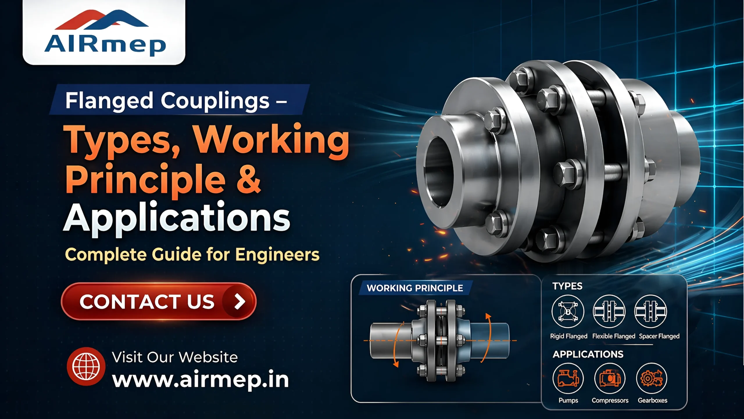
A flanged coupling is a mechanical device used to connect two rotating shafts to transfer power and torque. Even in 2026, they are the workhorses of heavy-duty machinery thanks to their high torque capacity and rugged design. Usually they are two flanges mounted on the ends of shafts and tied together with a ring of bolts.
In mechanical engineering and industrial machinery, the need for two shafts to transmit power is very important. This could be from a large water pump to an industrial electric motor to use, so it’s necessary that all parts used to connect the shafts together provide strength, reliability, and precision. This is where flanged couplings become relevant. As we transition into 2026, there is a growing demand for high torque, so understanding how these couplings function through their mechanical properties will be significantly important.
Table of Contents
What is a Flange Coupling?
Prior to discussing anything technical, it is worth taking a brief moment to clarify a common source of confusion: the flange and coupling difference.
- A flange is defined as a flat disc or cylindrical collar designed to provide additional strength or to attach to an object.
- A coupling is simply an item used for connecting two shafts together at their endpoints for the purpose of transferring power.
In this case, a flanged coupling consists of two flanges that have been “keyed”, one from each shaft, which are bolted together as one complete unit forming a secure, solid connection.
Flange Coupling Working Principle
The flange coupling working principle depends on the tough transmission of torque through conflict and mechanical locking. Here is how it works in easy steps –
1) Attachment – Each shaft has a flange attached to it. A “key,” a piece inserted into a groove (keyway) on both the shaft and flange hub, holds the flange in place so it does not slip.
2) Alignment – The two shafts are connected by aligning the faces of the flanges. Correct alignment is crucial to prevent vibration.
3) Securing – The two flanges are fastened together using bolts and nuts.
4) Torque Transmission – The driving shaft turns, sending power through the key to the first flange, through the bolts to the second flange, and finally through the second key to the driven shaft.
In many industrial flange coupling structures, one flange has a protruding “tongue,” and the other is recessed. This facilitates perfect centering of the shafts during the installation process.
Flange Coupling Types
Not all industrial backgrounds are the same, which is why there are three primary flange coupling types typically utilized today –
1. Rigid Flange Coupling
The rigid flange coupling is the simplest and most widely used type of flange coupling. With this type of coupling, there is no flexibility for shaft movement as they are rigidly coupled. The only time these types of couplings are used is when both shafts are in precise alignment prior to installation.
2. Unprotected Flange Coupling
Unlike the protected coupling, the unprotected flange coupling has bolts and nuts that are exposed on the surface of the assembly. They are easier to maintain than the protected type, but present an additional hazard as the bolted connection may become snagged by clothing or safety glasses if the person working with the machinery gets too close to the flanges. In most cases, they will only be used on enclosed machinery where no one has access to the area while the machine is in operation.
3. Protected Flange Coupling
A protected flange coupling is designed with safety in mind. The design incorporates thick flanges around the bolt heads and nuts to provide protection from contact or injury to personnel working near the machine(s). The roundness of the outside surface of the flange also offers a safety advantage; if an operator comes too close to the rotating shaft on the flange, the round flange will minimize potential injury caused by contact with a rotating object at high speed.
Comparison at a Glance
| Feature | Rigid Flange Coupling | Protected Flange Coupling | Unprotected Flange Coupling |
| Safety | Medium | High (Bolts are covered) | Low (Bolts are exposed) |
| Alignment Required | Perfect | Perfect | Perfect |
| Maintenance | Simple | Moderate | Very Easy |
| Primary Use | General Power Transmission | Open Industrial Floors | Enclosed Gearboxes |
Flange Coupling Advantages and Disadvantages
Advantages –
- Handles high torque output – The bolted construction allows for heavy amounts of power without slipping.
- Easy to install – Assembly and disassembly for maintenance requires relatively little skill or use of special tools.
- Long life span – Generally made of cast iron or mild steel, industrial flange couplings have a very long service life.
- Provides a very “stiff” connection – The rigid nature of flange couplings allows them to form very accurate connections between two pieces of machinery, a vital characteristic of precise machines.
Disadvantages –
- Alignment Issues – Misalignment can lead to failure because flange couplings cannot take any misalignment. Even a small amount of misalignment will lead to failure of the coupling or the bearings supporting the coupling. In such cases, flexible solutions like grooved couplings are preferred as they can absorb minor misalignment and reduce stress on connected components.
- Size and weight – Flange couplings are usually considerably larger and heavier than alternative coupling types. For compact or space-constrained systems, threaded couplings are often a better choice due to their smaller size and ease of installation.
- Vibration – Flange couplings do not provide any shock or vibration absorption between the motor and load; hence, they should be installed in areas where vibration levels are minimized.
Flange Coupling Applications
Flange coupling applications can be found in many of the greatest nations on earth due to their ability to withstand heavy loads. Flange couplings will typically be used for the following applications in 2026 –
1. Pumping Stations – Large electric motors will often be connected to water pumps.
2. Marine Engineering – The engine will be connected to the propeller shaft of a vessel.
3. Large Industrial Blowers – The flanges are used to connect to large HVAC and ventilation systems.
4. Power Generation Facilities – Turbines will be connected to generators to generate power.
5. Textile Mills and Paper Mills – Flange couplings are used on long line shafts where speed is constant.
It will be essential to verify that flange couplings in the United Arab Emirates and the Middle East conform to international standards. Companies looking for high-quality engineering/industrial parts can count on Airmep Sales Corporation for a multitude of solutions that meet their demanding engineering needs.


Conclusion
For engineers and facility managers who work with heavy machinery, having knowledge of how a flange coupling works is critical. While this type of coupling is dependent on precise alignment to operate correctly, flange couplings can be used within machines to transfer huge quantities of power and therefore form the backbone of industrial machines. In addition to selecting between a protected flange coupling (for safety) and a rigid flange coupling (for efficiency), companies have options regarding their flange couplings and can choose both to maintain the operation of the business.
FAQs
Can a flange coupling handle shaft misalignment?
No. They are stiff couplings. If your shafts are not perfectly aligned, you need to use a flexible coupling. If you force the alignment on a rigid set-up, you will shear the bolts or burn out the motor bearings.
What material is typically used for an industrial flange coupling?
Most are made from premium Cast Iron (general use) or Cast Steel (heavy-duty or high-stress applications). In 2026, some specialized industries also use alloy steels for greater resistance to rust.
Why is it called a “protected” coupling?
It is called protected because the design includes a protective flange rim that recesses the bolt heads and nuts below the surface. This ensures they won’t catch on to any outside objects or people while rotating.
How is the torque actually transferred?
Through the key and bolts, torque is transferred from the shaft to the hub. Power transfer is also enhanced by friction between the two flat faces in high-torque models.
How do I maintain a flange coupling?
A regular check of the bolts’ tightness and replacement of worn keys are part of maintenance. It is not necessary to lubricate the coupling internally because it contains no moving parts.
Also Read: What Is a Fire Pipe Coupling? Types, Uses & Benefits